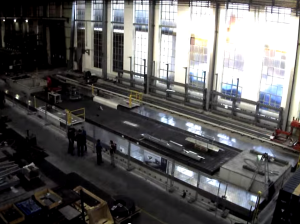
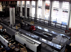
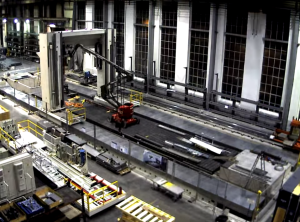
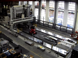
How do you assemble a giant machine tool? Very carefully. A lot of thought needs to be put into the machine design early on to accommodate assembly, alignment, shipping, and installation. Simple things like providing lifting points and making sure fasteners are easily accessible can help things go smoothly in the field.
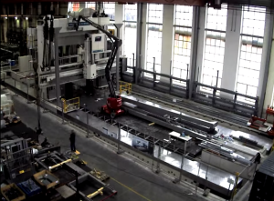
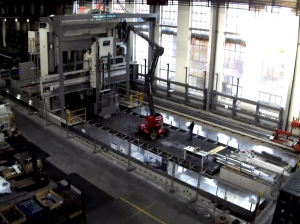
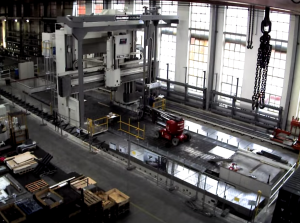
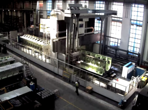
The above video shows a time lapse of the installation of a Waldrich Coburg Powertec gantry style machining center for customer MAN Diesel. There’s a lot going on so I’d like to break down the individual installation steps.
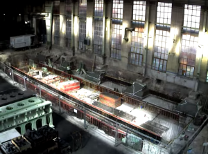
Pouring the Machine Foundation
The installation starts with the machine bed foundation. This is the foundation that will support the X-axis beds and ultimately the entire machine weight. A thick foundation with a lot of reinforcing bar is important to minimize deflection in concrete due to the machine movement and operation. Any deflection or settling in the foundation will ruin the machine precision relative to the workpiece.
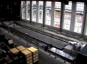
Pouring the Workpiece Foundation
The workpiece requires an isolated bed foundation. Similar to the machine bed foundation, stiffness is the key. Any deflection in either of these foundations relative to one another will ruin the machine precision.
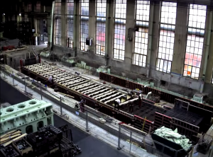
X Beds
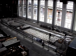
Installation of the X beds is an important step and one they appear to skip over in the video. The X beds are anchored to the bed foundation and will ultimately form the X-axis of the machine. The beds support and guide the machine with linear rail. Straightness of this rail is critical to the machine precision and must be adjusted during installation using jacking screws built into the beds. Some of this process is shown in the video. Gear rack for driving the machine must also be adjusted and spaced correctly during this process.
Installation of the workpiece fixturing plates is also shown during this stage.
Waycovers
The X axis way covers are installed to keep chips and debris away from the X rails. Interesting they’re installed this early, they can dent easily.
X Axis Carriages
The X axis carriages are lifted and mounted to the X rail. It depends on the style of rail but the bearing cars are likely already installed onto the rail and carriages are bolted down to the cars.
Z Towers
The gantry legs with integrated Z axis are installed next. They’re flown in via the overhead crane, stood up, positioned and installed onto the X carriages. It appears that all of the necessary fasteners are installed prior to the legs being set into place.
Y Bridge
The Y bridge is flown into place and ties the two gantry legs together. This takes some coordination with the crane operator and some time spent in the man-lift. The maintenance platforms and electrical cabinets also appear to be installed behind the gantry during this process.
Y Axis
A tricky part of the installation. It looks like they place the Y-axis on blocks during the installation process. Careful positioning is required to attach the Y-axis to the bearing cars and ball nuts on the tower legs. It’s important to make sure these fasteners are easy to access during the design phase.
Z Ram
The Z-ram is bolted onto the Y-axis without a lot of hassle. The assembly is lifting by red painted installation tooling bolted to the sides of the lower assembly. Note the whole Y axis assembly is still resting on blocks.
Operator Platform
A movable operator platform is installed and bolted onto the front of the machine. This makes getting right up to the tool point easy for the operator. I’m speculating that this is for automated tool changing as well.
Alignment
Axis alignment occurs before all the final way covers and bellows are installed. Important to make sure everything has been installed correctly and running smoothly. Most of the axes are modular but there can be some tricky alignment in the Z-axis due to the tandem configuration.
Assembly Complete
Minor details such as decking and cell guarding are installed, the machine is bought off in a factory acceptance test, and everyone gets to go home!

